
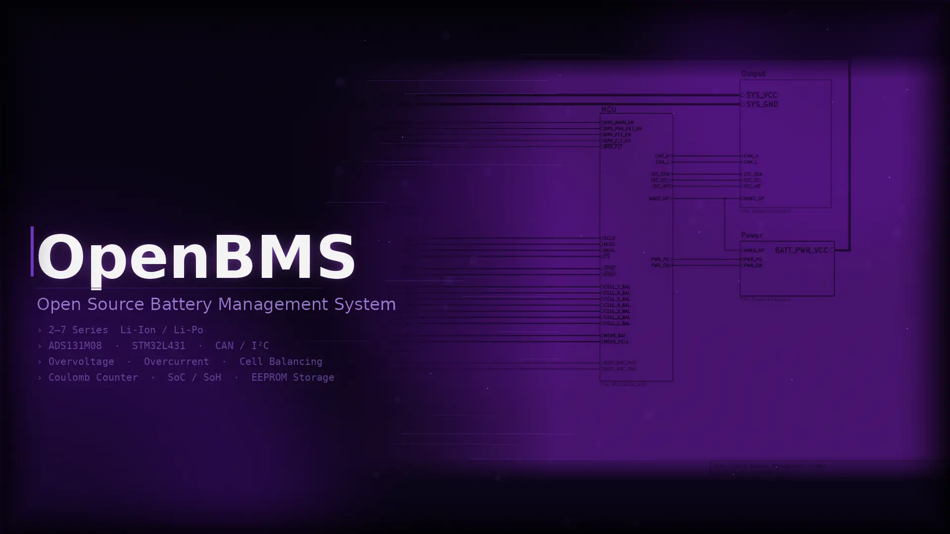
OpenBMS Hardware
OpenBMS is an open-source battery management system for 2 to 7-cell Li-Ion and Li-Po battery packs. A fully integrated hardware and firmware solution for battery management and protection, providing:
- Fuel gauge — measure battery capacity, state of charge, and state of health
- Learning algorithms — learns battery behavior and adjusts management accordingly
- Cell balancing — keep multi-cell voltages in sync to prevent drift over time
- Protection — guard against overcharging, overdischarging, overheating, and short circuits
- Communication — talk to chargers, displays, microcontrollers, and other devices
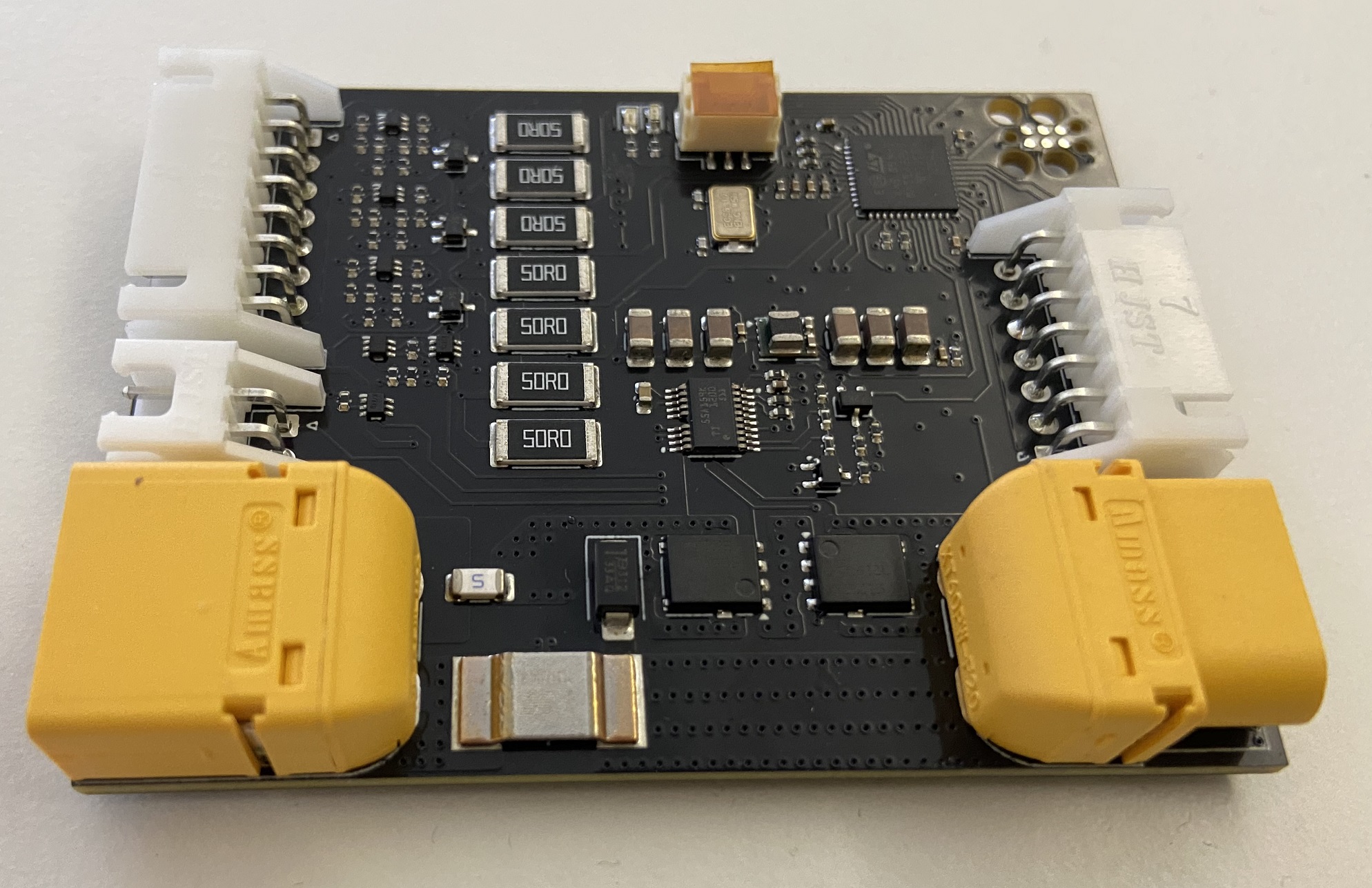
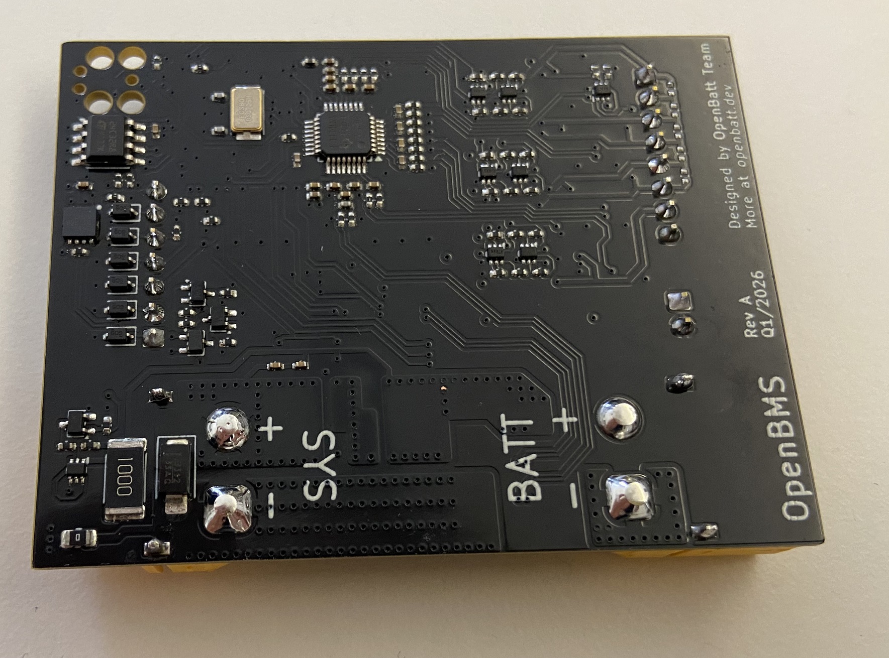
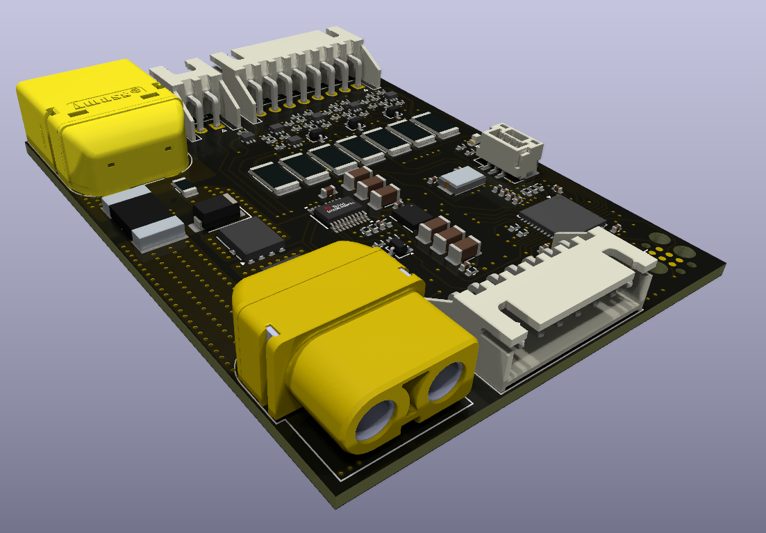
OpenBMS In Action
Features
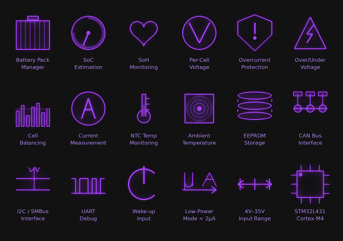
- 🔋 Supports pack voltages up to 30V and continuous currents up to 16A.
- ⚡ State of Charge (SoC) estimation using coulomb counting
- 🩺 State of Health (SoH) monitoring with capacity fade tracking and internal resistance estimation
- 📊 Per-cell voltage monitoring with 24-bit resolution
- 🔌 Pack and cell overcurrent protection up to 20A hardware trip (adjustable threshold)
- 🛡️ Overvoltage and undervoltage protection (adjustable thresholds)
- 🔀 Passive cell balancing for up to 7 cells
- 🔵 Battery current measurement via precision shunt resistor
- 🌡️ NTC thermistor input for battery temperature monitoring
- 🌡️ On-board ambient temperature monitoring via MCU and ADC internal sensors
- 💾 Non-volatile storage of SoC, SoH, impedance, fault history, and charge profiles (EEPROM)
- 🚌 CAN bus communication interface (up to 1 Mbit/s)
- 🔗 I2C communication interface for host integration (SMBus compatible)
- 🖥️ UART debug interface
- 🔔 Wake-up input with power-on latch for low-power system control
- 🔋 Power-down mode quiescent current < 2 µA
- 🖥️ Based on STM32L431 ARM Cortex-M4 microcontroller
Overview
OpenBMS and the battery are designed to be a single, inseparable unit. Ideally, they are connected on the first day of the battery’s life and stays throughout its entire lifetime. This way, OpenBMS learns the battery’s characteristics over time and continuously tracks its state of health and other parameters.
It protects the battery from overcurrent, overvoltage, and undervoltage conditions, and balances cells to maximize pack lifetime. State of charge estimation tells you exactly how much energy you have left, while long-term health monitoring tells you when it’s time to replace the battery.
The battery communicates with the host system via CAN bus or I2C. Through OpenBMS, the battery can:
- Give energy to the system (discharge)
- Take energy from the system (charge)
OpenBMS can be easily described with the following block diagram:
+---------------------------------------------------------------------------------------------------------------+| OpenBMS || || +-----------------------+ power +-------------------+ power +-------------------------+ || | Battery Input |<=============>| Switch Circuit |<=============>| Output | || | - - - - - - - - - - - | | - - - - - - - - - | | - - - - - - - - - - - - | || | + XT60 pwr connector | | + Main NFETs | | + XT60 pwr connector | || | + 8-pin JST (balancer)| | + Precharge FETs | | + JST (I2C,CAN,WAKE_UP) | || | + 2-pin JST (NTC) | +--------+----------+ +-------------------------+ || +-----------------------+ | ^ || | | ctr signals | can, i2c, wake_up || | cells v | || +---------------------+ SPI +-------------------------+ | || | Analog Block |<==============>| Digital Block |=======================+ || | (ADS131M08) | | - - - - - - - - - - - - | || | - - - - - - - - - - | | + STM32L431 (Cortex-M4) | || | + Cell voltage x7 | | + EEPROM | || | + Pack voltage | | + LED indicators | || | + Current | | + SWD / UART debug | || | + PFETs cell switch | | + I2C / CAN interfaces | || +---------------------+ +-------------------------+ || ^ || | 3.3V, wake_up || +----------+---------+ || | 3.3V Power Supply | || | - - - - - - - - - | || | + Buck converter | || | + Enable latch | || +--------------------+ || |+---------------------------------------------------------------------------------------------------------------+Battery Input
The battery input block consists of an XT60 connector for the main power, an 8-pin JST connector for cell voltage monitoring and balancing, and a 2-pin JST connector for the NTC thermistor input.
Switch Circuit
The switch circuit consists of main NFETs for connecting the battery to the output (system) and an NFET controller, the TPS1200. The TPS1200 is a Texas Instruments high-side NFET driver. When the NFETs are turned on, the battery is connected to the output and can supply energy to the system or be charged by the charger. When the NFETs are turned off, the battery is disconnected from the output.
Besides switching the NFETs, the TPS1200 also has built-in overcurrent, undervoltage, and overvoltage protection. It is important to note that these protections are hardware-based and are configured by setting resistor and capacitor values. This means they work even when the MCU (STM32) is off, which is a crucial safety feature. By default, the protections are set as follows:
- Overcurrent protection: 20A (adjustable by changing the sense resistor value and ISCP resistor)
- Undervoltage protection: 17.5V or 2.5V per cell (adjustable by changing the undervoltage threshold resistor divider)
- Overvoltage protection: 30.1V or 4.3V per cell (adjustable by changing the overvoltage threshold resistor divider)
- Auto-retry after overcurrent fault: the overcurrent fault will trigger after 13ms of overcurrent and will not auto-retry (adjustable by TMR capacitor and resistor)
The switch circuit also includes:
- Precharge/predischarge PFETs, which are optional. They are used to slowly charge the output capacitors to prevent inrush current (discharge direction) or to slowly precharge the battery (charge direction) in case of a very depleted battery. Precharge/predischarge current is limited by a 100Ω resistor and can go up to 120mA.
- A burn-out fuse for overcurrent protection in case of NFET failure. In case of a short circuit, the fuse will blow and disconnect the battery from the output, preventing further damage and a potential fire hazard. The fuse is rated for 25A and can be reset by replacing it.
Analog Block
The analog circuit is based on the ADS131M08, a 24-bit, 8-channel simultaneous-sampling ADC by Texas Instruments. The ADC circuitry does the following:
- Measures all 7 cell voltages individually across resistor dividers (0.1% tolerance)
- Measures overall pack voltage across a resistor divider (0.1% tolerance)
- Measures battery current via a shunt resistor (2mΩ, 0.5%, ±25ppm/°C) — nominally up to 16A
- Connects/disconnects cells from ADC inputs using PFETs to eliminate leakage currents when OpenBMS is off
- Balances cells by bypassing current from higher voltage cells through 50Ω resistors by controlling PFETs (controlled by MCU)
Digital Block
The digital block is based on the STM32L431 ARM Cortex-M4 microcontroller. It does the following:
- Reads cell voltages, pack voltage, and current from the ADC via SPI
- Reads battery temperature from the NTC thermistor via an ADC channel
- Controls cell balancing PFETs via GPIOs
- Controls the switch circuit (main NFETs and precharge/predischarge PFETs) via the TPS1200 controller
- Communicates with the host system via CAN bus or I2C
- Stores all battery information and profiles in EEPROM
- Provides LED indicators for battery status and faults
- Provides SWD and UART debug interfaces for development and troubleshooting
- Implements all battery management algorithms, including SoC estimation, SoH monitoring, fault detection, and others
3.3V Power Supply
The 3.3V power supply is based on Texas Instruments’ LMZM23600V3 buck converter, which steps down the battery voltage to 3.3V. The power supply also includes an enable latch which allows the MCU to completely cut off power to the digital block when OpenBMS is off, reducing quiescent current to less than 2 µA.
Output
The output block consists of an XT60 connector for the main power and a JST connector for communication and wake-up signals. The output is designed to be connected to the host system and/or charger. Through the output, the battery can supply energy to the system (discharge) or take energy from the system (charge). Communication with the host is done via CAN bus or I2C, while the wake-up signal can be used by the host to wake up OpenBMS from shutdown mode.
Characteristics
| Parameter | Value |
|---|---|
| Cell count | 2 to 7 cells |
| Supported chemistries | Li-Ion, Li-Po |
| Communication interfaces | CAN bus (up to 1 Mbit/s), I2C (SMBus compatible) |
| Maximum pack voltage | 30.1V (7 cells × 4.3V) |
| Minimum pack voltage | 4V (2 cells × 2V) |
| Maximum continuous current | 16A |
| Maximum peak current | 20A (hardware trip) |
| Current consumption (active, 7-cell, max) | 6mA |
| Current consumption (active, 7-cell, typ) | 4mA |
| Current consumption (active, 2-cell, max) | 19mA |
| Current consumption (active, 2-cell, typ) | 13mA |
| Power-down quiescent current | < 2 µA |
| Operating temperature range | -40°C to 85°C |
Why BMS Is Necessary?
Check the blog post page!
License
OpenBMS is licensed under the MIT license and CERN OHL-S v2.
← Back to projects